Overview
As climate change drives more frequent and intense storms, protecting large door openings has become a critical concern for commercial and industrial properties.
This Storm Shutter is engineered to withstand wind speeds exceeding 200 km/h (125 mph)—equivalent to a Category 3 hurricane. Independently tested to ASTM E330/E330M standards, it offers proven performance under extreme pressure conditions (up to 2.5 kPa).
Whether facing sustained winds or sudden gusts, the Storm Shutter is engineered to stay secure, absorb impact, and protect your property.
Storm Shutters provide:
- Double-walled slats reinforced with steel rods
- Steel cables vertically link slats and anchor to the barrel and floor
- Bottom shoes engage floor restraints for full anchoring
- No reliance on door jambs—making it suitable for diverse building types
Applications
- Port and Dock Buildings
- Coastal Buildings
- Aircraft Hangars
- Logistics Hubs
- Warehouse and Distribution Centres
- Manufacturing Plants
| STANDARD SPECIFICATIONS |
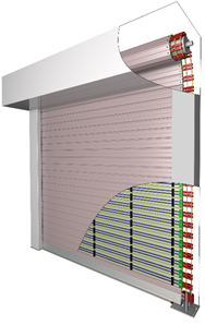
Drum Assembly
The barrel assembly consists of an extremely rigid steel tube sheathed over a pair of drive shaft assemblies fitted to heavy duty bearing sets and supported at both ends by steel head plates. The drive shaft is a solid polished steel round bar incorporating key ways to accept the drive sprocket. Corresponding to the size of the shutter, the head plates are either 6mm or 8mm thick with shafts of either 38mm or 50mm diameter.
Self-Supporting Design- The shutter incorporates its own structural support in the form of a ‘goal post’ formed by steel “C” channels. The entire drum assembly shall rest on the vertical members, with the end plates attached to the lintel for stability. The bulk of the shutter weight is thus transferred to the floor.
Curtain
Curtain Slats
The door curtain consists of 80mm x 20mm thick double-walled steel roll formed interlocking cavity slats. The slats are reinforced with steel rods spanning the entire length of the slat. Proprietary steel double-eyelet structures shall be attached to each end of the steel rods to receive the restraining cables.
Bottom Rail
The bottom slat is coupled to an aluminium profile base and fitted with a finned PVC weather seal. Attached to each end of the bottom slat are steel sliding ‘shoes’ that are part of the restraining mechanism. These shoes are connected to each other by steel rods spanning across the entire bottom slat. Restraining Mechanism A pair of stainless-steel cables are threaded through the eyes of the eyelet structures on each side of the door curtain. One end of each cable is attached to the steel tube of the barrel assembly while the other terminates into compression sleeves that are housed within the respective sliding shoes. Vertical guide posts on each side of the door will ensure that the door travels up and down in a straight line. Upon reaching the fully-closed position, the sliding shoes will automatically engage the steel restraints on the floor plate, thus anchoring the bottom rail to the floor plate and prevent dislodgement under wind pressure
Guide
The removeable guide covers are fabricated from steel sheets. They are bent and shaped to cover the edges of the door curtain and secured to the vertical shutter supports. Note: The guide covers are non-structural and serve an aesthetic purpose only.
Operation
Motor Drive
The drive unit consists of a suitably-sized linear drive motor operator mounted parallel to and behind the door roll. It has an integrated gearbox and a chain operated sheave wheel for manual operation in case of power failure. The control box is lockable, housing a set of push buttons for Up’, ‘Down’ and ‘Stop’ operations. The door operation shall automatically stop at the desired upper and lower limits via adjustable limit switches.
For safety reasons, the ‘DOWN’ button shall require the operator to push and hold when closing the shutter. This is to ensure the closing operation is being supervised. Upon sighting an obstruction, the operator will automatically release the push button by reflex. This action will instantly stop the downward travel of the shutter and prevent accidents.
Power supply shall be either Single Phase 230V x 15amp or 3-Phase 415V x 20amp,depending on the size of the shutter
|
Tested and achieved:
- AS4055 Wind Classification C1 (Cyclonic) Pt = 2.98kPa.
- Test specimen size: W 6.0m x H 3.0m.
- ASTM 330E/330M up to 2.5 kPa.
- Test specimen size: W 6.0m x H 5.0m